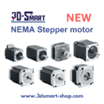
NEMA Stepper motor NEW 1pcs
NEMA Stepper motor NEW
EGP700
Description
Good quality stepper motors have a very high reliability, so the main cause of motor failure is usually external, usually related to the power driver or the connection.
Stepper motors
Stepper motors are a type of continuously rotating motor. The rotation occurs in discrete jumps of a given angle. It is a motor halfway between a standard DC motor and a servo motor. Like DC motors, they allow multiple 360 ° turns, while allowing precise angular positioning, like servo motors.
The most commonly used in 3D printers are bipolar hybrid stepper motors, usually in NEMA17 or NEMA23 format. Hybrid motors combine the small stepper capability of VR motors with the high inertia capability of permanent magnet motors. On the other hand, bipolar motors provide higher torque and anchorage than unipolar motors while being lighter in weight and smaller in size, however they require specific power controllers.
When selecting a stepper motor, we must know its main characteristics:
- Step: This is the minimum angle that the motor can rotate directly (without the use of microstep controllers). We can usually find motors with steps of 1.8 º or 0.9 º. In general, a smaller step implies greater precision, but also a lower maximum rotational speed.
- Working current: This is the maximum current value at which we must feed the motor for it to work properly. The more current we apply to the motor, the more torque we will achieve and therefore it will be able to withstand greater inertia without losing steps, however, there will also be greater heating and wear. Using currents higher than those specified by the manufacturer will cause deterioration and failure of the motor.
- Voltage per phase: This is the voltage required by each of the coils to operate correctly.
- Phase resistance: This is the electrical resistance provided by each of the coils.
- Phase inductance: The maximum inductance value generated by each of the coils when activated.
- Positioning accuracy: The maximum deviation that can occur during a rotational movement. In general, a lower value represents higher accuracy.
- Maximum operating temperature: This is the maximum operating temperature that the motor can withstand. Exceeding this temperature for extended times will result in motor failure.
- Rotor inertia: This is the inertia provided by the rotor when empty due to its own weight. The inertia supported by the motor will be the sum of this plus that of the elements coupled to the motor.
- Torque or holding torque: This is the maximum torque that the motor can withstand when the phases are inactive (no current), without causing the shaft to rotate.
- Anchor torque: This is the maximum torque that the motor can withstand when it is stopped and the phases are active (live), without causing the shaft to rotate. The value is considered for a motor supplied with maximum current.
- Starting torque: This is the torque necessary to overcome the inertia of the rotor so that it starts to rotate.
- Turning torque: This is the maximum torque that the motor can withstand when it is rotating without causing step loss. The value is considered for a motor supplied with maximum current.
If we are looking for a motor that allows us to use high speeds and withstand high inertias during movement, for example in the case of XY axes, we should choose a motor with 1.8 º steps and high torque.
The Z-axis motor will not require high working speeds, so a 0.9 º motor will provide smoother movements. In this case, a motor with maximum holding and anchoring torque should be chosen to support the weight of the platform or gantry (depending on the design of the printer).
Connection of bipolar stepper motors
When connecting stepper motors correctly, it is useful to have the manufacturer’s specification sheet available, as the position of the wires varies from one model to another.
Typically, a bipolar stepper motor will have 4 connections consisting of two independent power supply circuits. Each circuit consists of a positive and a negative pole supplying power to each of the motor’s coils.
The first thing to know is the position of these four connections on our printer control board. We can find two types of nomenclature on the control boards. The first is 1A 1B 2A 2B, where each number represents a circuit and the letters A and B represent the poles. The second is A A– B B– where each letter represents a circuit and the accent represents the negative pole.
Once the connections on the board have been determined, the same must be done for the motors.
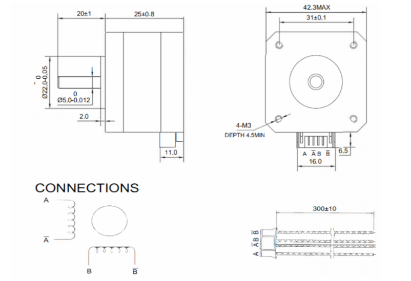
Image 2. Example of connections on a NEMA17 motor specification sheet. Source: Bondtech
If a specification sheet is available, the order of the wires in the connector should be consulted. In this case, the nomenclature A A– B B– is the most common.
In the case that the board and the motor use the same nomenclature, the connection is as simple as pairing each terminal. If they use different nomenclature, they must be paired as follows:
- 1A – A
- 1B – A–
- 2A – B
- 2B – B–
If no motor data sheet is available, the connection pair of each spooll must be determined. This is done by measuring the resistance at all possible combinations of connector pin pairs. When the resistance is not infinite, the first pair has been located. The most common combinations used by motor manufacturers are 1-3 4-6 or 1-4 3-6, so start by testing these two combinations.
Once located, each phase is connected to each of the spools. It is important that the two phases are connected to the coils in the same polarity, so if we have placed them in inverted phase, when sending current to the motor it will not move and will emit a noise. In this case the polarity of one of the coils must be reversed.
It is very important to keep both phases separate, so the condition of the connectors should be checked frequently. A bad contact or a bridge between phases will cause the motor to stop working.
Setting the current of the motors
Stepper motors are powered through specific controllers or drivers. There are many different models on the market. The higher quality ones will generally provide longer durability and quieter operation.
Within the models available, there are two methods of adjusting the current sent to the motors:
- By means of an adjusting screw. In general, lower quality or cheaper drivers allow the output current to be adjusted by means of a potentiometer in the form of a screw. In this case it is necessary to use a multimeter and a precision ceramic screwdriver to make the adjustment.
In this case the adjustment can be made in two ways:
- By Current: With the printer switched on and the motors connected, the current in one of the phases will be measured and adjusted to the appropriate value. This method is not recommended, especially the first time a new driver is connected, as the motors are initially powered without knowing if the output current is higher than the current admitted by the motor.
- By reference voltage: This is a slightly more complex method, but more recommendable. First we must determine the required reference voltage using the formula:
max · 8 · Rs
Where Imax is the maximum current at which the motor will be powered (usually at most 90 % of the maximum specified by the manufacturer) and Rs is the detection resistance of the driver.
To adjust it on the driver, simply power up the driver, measure the voltage between the Vref pin (usually the potentiometer itself) and a ground pin (usually the power supply pin) and set the appropriate value using the potentiometer.
- By firmware: Many current drivers do not have an adjustment potentiometer and allow the output current to be set directly by firmware. To do this, simply set the appropriate current value in the motor section of the firmware.
When selecting the output current of the drivers, it is not advisable to use the maximum value determined by the manufacturer. In order to prolong the service life of the motors, do not exceed 90 % of the manufacturer’s maximum value, the optimum being the minimum current required to generate sufficient torque to withstand the inertias.
Higher current, in addition to higher torque, also means higher heating, higher motor noise and higher wear.
Maximum speed of a stepper motor
Stepper motors advance by pulses, so the maximum speed of the motor will depend on the maximum signal frequency that the control board is able to send. In addition, it must be taken into account that usually several motors are working simultaneously, so the frequency for each one will decrease.
For example, if the control board works at 100000 Hz and 4 motors (X,Y,Z and extruder) are working simultaneously, each motor will be controlled at 25000 Hz, or 25000 pulses per second. This means that a 1.9 ° motor without microstepping can rotate at a maximum of 125 rps. In a GT2 8-tooth belt drive system (the most common) this translates into a theoretical maximum linear speed of 3600 mm/s.
In the case of microstepping, the maximum speed would be reduced proportionally, so that if 16 microsteps are used, the maximum speed would be 225 mm/s, but if 256 microsteps are used, it would be reduced to only 14 mm/s.
It is very important to know the operating frequency of the control board, as the combination of a low output frequency with a high microstep setting can cause the maximum allowable speed to be lower than the printing speed, resulting in a significant loss of steps.
Appropriate setting of the steps per mm
When the motion signal is transmitted to the motor, it is sent as a rotation, however the movements included in the print files are linear. This is why the printer must be able to translate the angular movement into a linear one.
The movement is generally transmitted by means of toothed pulleys and belts, so that the step/mm conversion depends on the diameter of the pulleys.
To calculate this, the following formula is simply applied:
steps/mm = (360/P) · MS
2 · π · Rpulley
Where P is the motor pitch, MS the configured microsteps (1 in case of not using microstepping) and Rpulley the radius of the pulley used.
In the case of screw-transmitted movements, it is the pitch of the screw that defines the feed rate. For this purpose, the following formula is simply applied:
steps/mm = (360/P) · MS
A
Where P is the motor pitch, MS the configured microsteps (1 in case of not using microstepping) and A the pitch of the screw thread.
There are also many calculators that make it easier to obtain these values, such as the one offered by Prusa Printers.
Once these values have been obtained, and although in theory they are correct, it is advisable to carry out a precise calibration to compensate for possible manufacturing or assembly defects.
For this purpose, a cube of known dimensions (e.g. 50 x 50 x 50 mm) shall be printed out and the actual dimensions measured. Once this is done, the following formula shall be applied:
steps/mm = Dtheorical · Pactual
Dreal
where Dtheorical is the theoretical size that the part should have, Pactual is the current P/mm setting and Dreal is the measurement value obtained from the printed part.
By introducing the new P/mm value, you should obtain parts with appropriate dimensions.


